
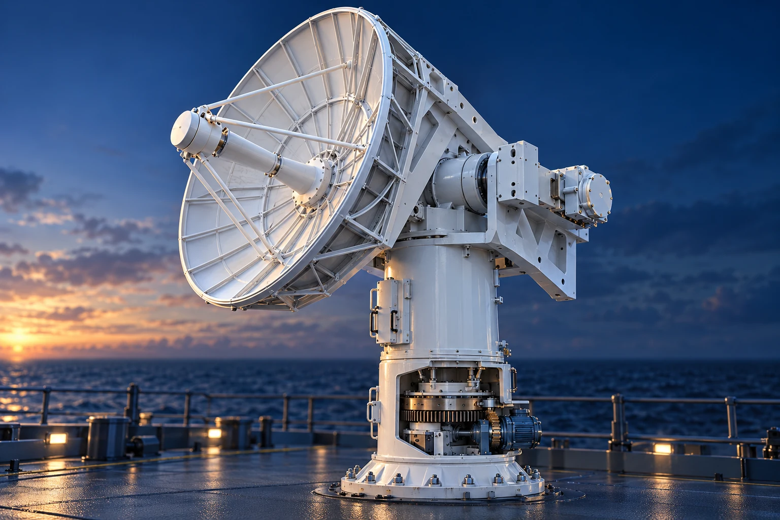
Naval electronics & systems diagnostics
Naval career foundation / Electronics / Diagnostics
THE VISUAL LANGUAGE
Original cutaway and thermal illustrations bring the components, mechanisms, and industrial environments behind the services into view.
This AI-generated illustration series uses public manufacturer images and technical references to guide recognizable equipment geometry. Selective cutaways reveal component relationships: a rotor inside a stator, a supported roll, and a furnace coil outside its refractory lining.
These are illustrative studies, not equipment photographs, engineering-validated drawings, operating instructions, customer projects, or depictions of employer facilities. Training documents and service decisions are developed from the actual assessed equipment and authorized information.
Naval career foundation / Electronics / Diagnostics
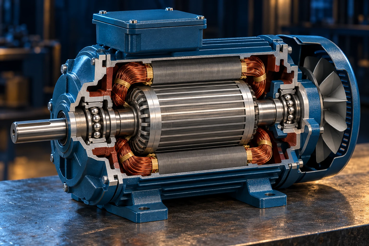
System function / Technical learning / Applied knowledge
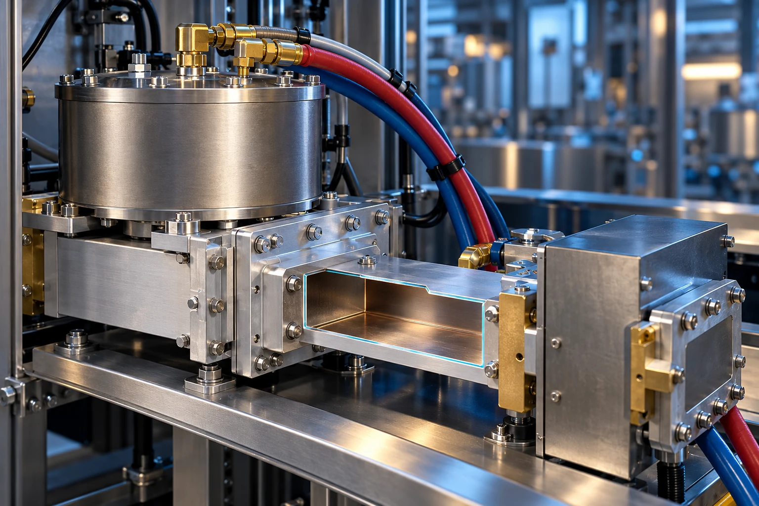
Microwave generation / Power / Process technology
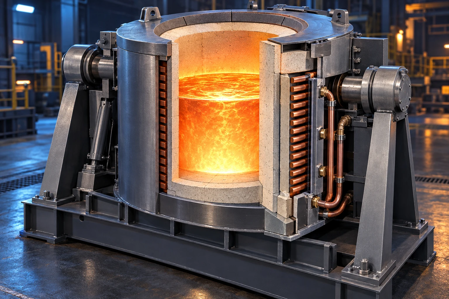
Induction melting / Heavy equipment / Plant systems
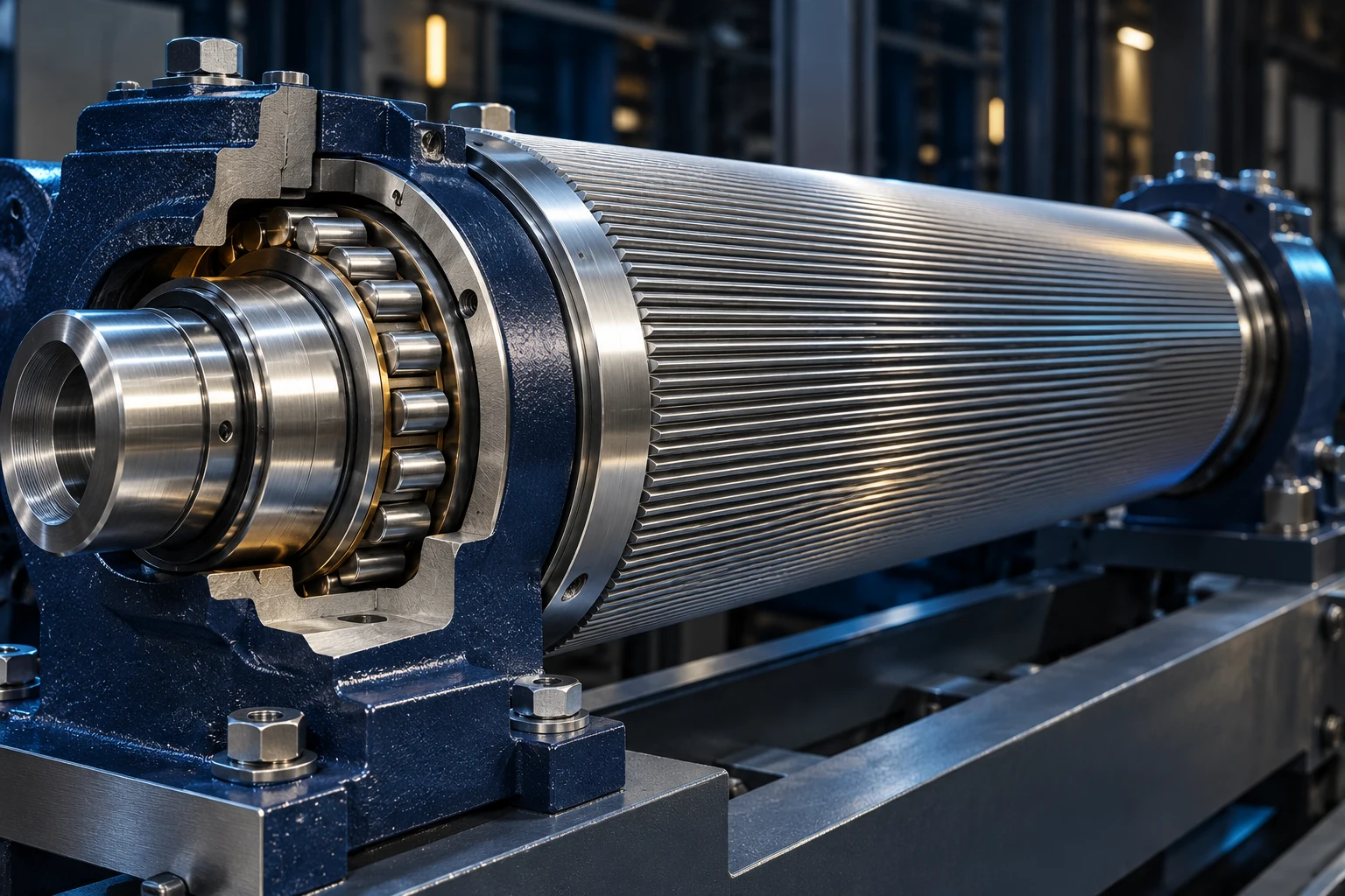
Corrugation / Converting / Precision mechanisms
Program structure / Work management / Technical readiness
The thermography artwork pairs optical and false-color infrared-style views of a motor, with a warmer bearing-housing region. It is a conceptual illustration, not a measured thermogram, a temperature reading, or evidence of an actual fault. A real inspection interprets surface observations alongside operating conditions, measurement settings, and equipment context.
The maintenance-program diagram shows relationships between equipment records, preventive-maintenance tasks, work orders, spare parts, and equipment history within a client-provided system. It is a conceptual relationship map, not a software product, a CMMS screenshot, a customer record, or a representation of an employer’s systems. Primary Industrial helps establish and improve the maintenance practices inside the system the client selects and provides.
The radar illustration accompanies prior naval technical experience. It represents the development of electronics and system-diagnostic skills; Primary Industrial does not offer military weapons, radar servicing, or classified work.
The five colored segments around the Primary Industrial π express Assess, Diagnose, Plan, Execute, and Verify. The labeled loop appears on the homepage and on the approach page.
CONTACT PRIMARY INDUSTRIAL
Describe the machine, the problem, or the capability your team needs. The starting point can be one piece of equipment or a wider maintenance and training need.
Requests are reviewed before work is scheduled. For an immediate safety hazard, follow your facility’s emergency procedures.